This controller is dedicated for hydraulic dynamometer.
It is a control measurement system that conduct measurement and feedback control of test piece by using hydraulic dynamometer.
It is equipped with measurement function for speed and torque, control function for speed and torque of test piece by manual or automatic, and alarm function that detects and processes system malfunction.
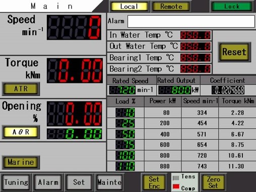
Touch screen sample
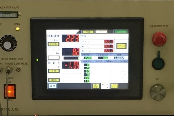
Dyno controller
Our dyno controller can control and measure by programmed operation from upper system.
And it supports expansion to existing system.
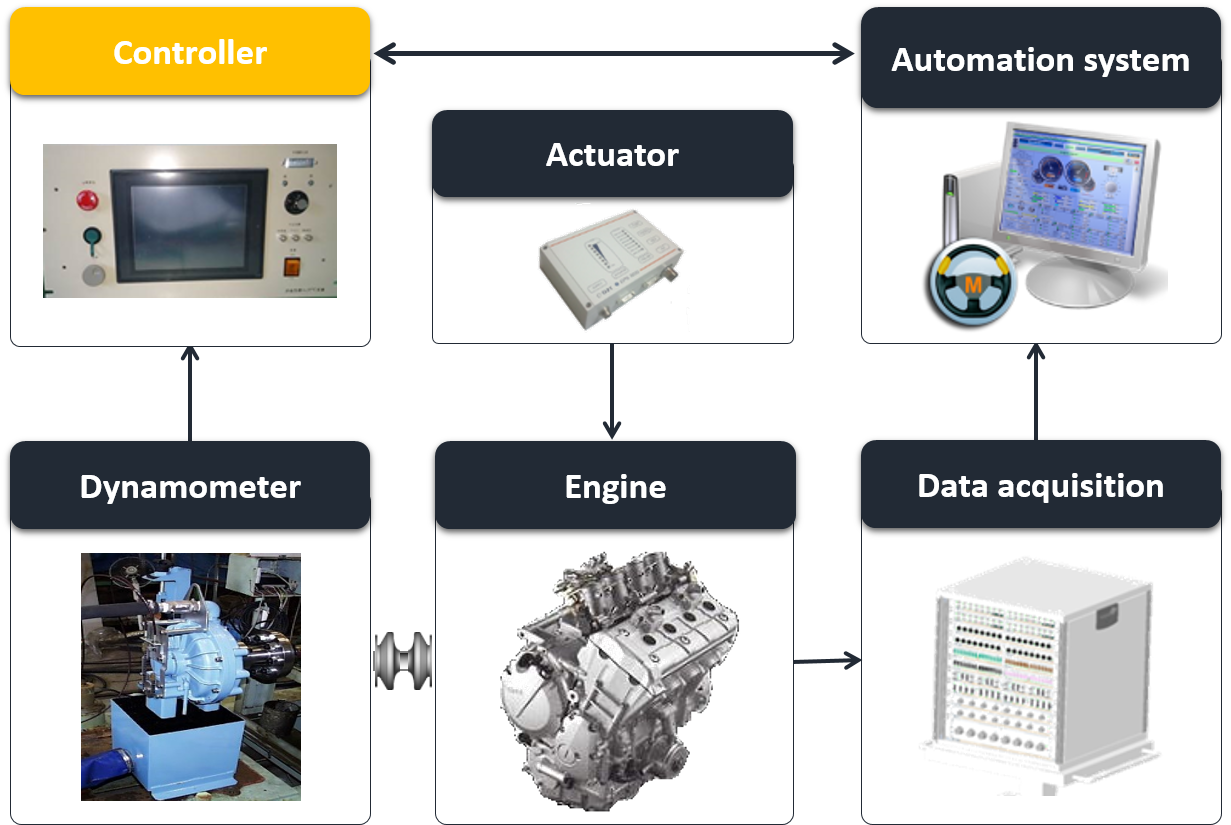
Standard test bed system (reference)
We can offer the most suitable testbed engineering to customers.
Please contact us for further details about automation of test bed, additional automation system, data acquisition sensors, test bed layout and shaft couplings.
We can offer the suitable proposal for your budget and request.
| Model | HDYC-400 |
|---|---|
| Control mode | Manual control: Adjusts the load opening of hydraulic dynamometer to control engine torque and speed by set value of the manual encoder dial. Constant speed control: Conducts feedback control to the set speed. Constant torque control: Conducts feedback control to the set torque. Marin characteristic control: Conducts cube control from the calculation of load by torque coefficient according to the square of speed. External control: Receives programmed operation from an upper system to conduct control and measurement. |
| * Control accuracy | * Control accuracy may not be within the range due to the condition of engine and dyno, setting of PID adjustment and effect of cooling water pressure. |
| Alarm setting and monitoring | Emergency stop: Conducts control stop with emergency button when abnormal condition. Overspeed: Monitors the upper limit of dyno. Overtorque: Monitors the upper limit of dyno. Inlet water temp: Monitors the cooling water temp. of dyno (30 °C). Outlet water temp: Monitors the outlet water temp. of dyno (60 °C). Bearing temp.: Monitors the bearing temp. of dyno (80 °C). External alarm: Monitors the external device with contact signal input. |
| External I/O | Analog voltage I/O (0-10V), analog current output (4-20mA), A contact signal |
| Necessary electric power | Three-phase AC200V, 50/60Hz, 15A |
| Size (mm) | Main body: W480 x H249 x D430 Mounted on rack: W520 x H543 x D600 |
| Mass | approx. 50kg incl. main body, rack and power panel |
| Model | TP-1000A |
|---|---|
| Manual operation | Manual load control: Push button controls the load operation motor and opens/closes the load valve to increase/decrease the absorbed torque. |
| Indicator accuracy | Speed indicator: Based on the indicator manufacturer. Torque indicator: Based on the indicator manufacturer. * Indicator accuracy may not be within accuracy range due to the condition of engine and dyno, setting of PID adjustment and effect of cooling water pressure. |
| Alarm setting and monitoring | Dyno oil lubrication: Monitors oil flow with galvanometer. When alarm generates, the position of engine throttle must be switched to idling while keep pressing the load decrease button to the lower limit. |
| External I/O | Analog voltage I/O (0-10V), contact signal |
| Necessary electric power | Three-phase AC200V, 50/60Hz, 15A |
| Size (mm) | Main body: W480 x H249 x D430 Mounted on rack: W520 x H543 x D600 |
| Mass | Main body: approx. 20kg (50kg when Incl. rack and power panel) |
* Specification is subject to change due to product modification.


The following pages are translated by a machine translation system.
Note that the machine translation system doesn't guarantee 100% correctness.
Some proper nouns might not be translated correctly.